Instromet Weather Instruments
Weather stations and weather monitoring specialists
Service
Weather station service & sensor repair – service & calibration facility overview
Instromet Weather Systems Ltd have a full facility for weather station service. This includes repair and calibration of all our weather products. Periodic servicing of all our weather stations helps to keep them running smoothly. This also help’s extend the products working life. Calibration of the features keeps the weather display accurate.
Weather station service – Initial fault checks
There are a number of initial checks you can make if you experience a problem with your Instromet products. Here we will list some of the known symptoms to look out for on our earlier products. You will find tips for investigating and resolving common problems with these older products.
Station service – further help
If nothing on this page covers the symptoms you are experiencing, then please contact. We can then arrange a weather station service here at our North Walsham workshop.
Weather station return packaging
Your weather station should be returned in sturdy as well as oversized box. Please use layers of bubble wrap, foam or other forms of packing materials to protect your equipment in transit. You can contact us for further advice on packing your equipment for return. We can also arrange carrier collection to be made direct from your home.
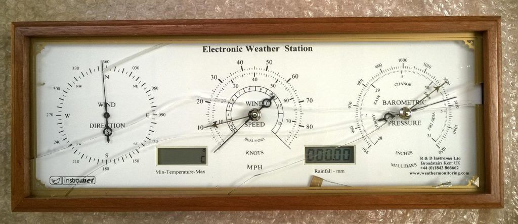
Unfortunately, from time to time, we do have units arrive with flimsy packaging. We have even received a display here before in nothing more than a jiffy bag! Unfortunately, thin packaging can result in expensive to repair damage as per the image below.
Weather station service Temperature display problems – display reading “LLLc”
One of our most common calls we get is in regards to temperature related problems.
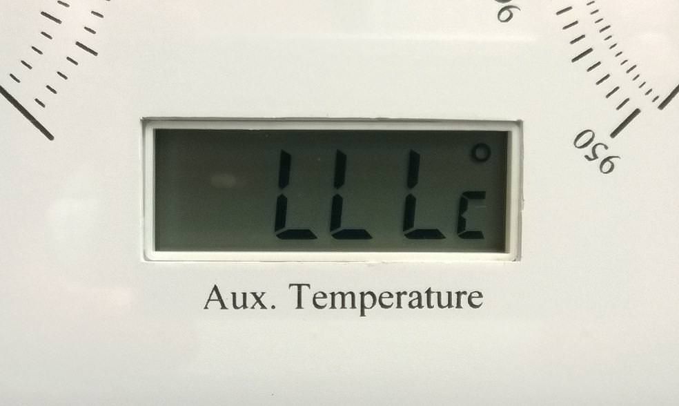
A display which shows “LLLc” generally indicates that the display has lost contact with the temperature probe. When this occurs, we normally recommend checking all connections to the temperature sensor on the ‘green’ and ‘white’ wires. Even cutting the cabling back a little and re-connecting with fresh cable is a good idea.
One cause of this on older units (pre 2004 generally) is that the wind sensor terminal block may have corroded. These can be replaced.
After the cable has been checked and re-worked if need be, we would suggest powering the system down. Once safely disconnected from the mains, removing the back up battery for a couple of minutes. This should help as sometimes the temperature display will ‘lock up’ rather than burst into life. Hopefully once power is then re-established, all should be OK.
If the display still shows “LLLc” then it may be a good idea to test the temperature probe itself. The below link gives the expected resistance measurements per temperature degree. When testing the probe, it is important to disconnect it from the rest of the system. If not any ohmmeter will measure the internal resistance of the rest of the system and give a false reading: Here is a temperature probe readings chart.
But it would be very rare for the “LLLc” to actually be caused by a display itself. Cabling and connections are the normally the cause of this type of problem.
Temperature display stuck on one reading no matter what is pressed
Carrying on with the temperature theme is the next issue. A temperature display “locked” on one reading with the buttons having no effect.
This problem is normally caused by a low back up battery within the display. This being the case we recommend replacement. Ensure the display is powered down at the mains. Remove the rear panel of the display via the four corner screws. Once the back panel is removed it should be possibly to see within the display the temperature display back up battery. This will either be a AA or AAA battery.
If this battery hasn’t been replaced for some time it may have has leaked and damaged the battery holder. If this has occurred then the display will need returning to us for a new holder to be fitted.
But hopefully once the battery has been replaced, the temperature display should, all being well, operate correctly once more. If it doesn’t come back on then the temperature display may need replacing. If this is the case, then it would be best to contact us to arrange workshop service.
Rainfall sensor problems
There are three types of rain sensor builds which we have supplied over the years:
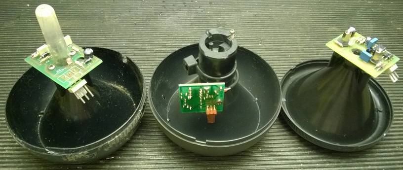
Rain sensor model type
Instromet has supplied three styles of rainfall sensors as shown above. The left hand sensor is the original R&D Electronics supplied unit. This then changed over to the centre Novomec version, with original part number 480 1000 040/01. The right hand unit is still the current build, with part number 480 1000 121/01. The funnel design and circuit layouts have changed over the years while each sensor still functions the same. They all operate from the same electronics and same specification. This means that all rainfall sensors supplied by Instromet are backwards compatible.
Rain sensor operation overview
The Instromet rainfall sensor is simple in operation. Rainfall is collected via the 80 mm funnel. This rainfall then passes through a pair of filters before dripping through an internal infrared beam at the exit of the funnel. Breaking this beam will cause the sensor to produce a pulse output in the region of 5 V DC per droplet. Once the water passes through the beam, it then exits the bottom of the sensor. When working correctly the sensor will produce 100 droplets of water per 1 mm of rainfall (Accuracy +/- 5%). This can be tested by applying 5 ml of water into the funnel manually. This should then produce 1 mm (+/- 5%) of rainfall on the wall display.
Routine rain sensor maintenance
The Instromet rainfall sensor requires regular maintenance to allow it to function both correctly and accurately. This mainly involves cleaning the filters at the base of the funnel. Its important to keep these filters clean as they prevent debris from blocking the 1 mm hole at the base of the funnel. They also help to regulate the water flow rate through the sensor. Removing them will cause water to trickle through the sensor rather than drip. If this happens you will get a reading lower than expected. Its also important to clean the 1 mm hole at the base of the funnel from time to time. Failure to do so will result in this slowly closing up due to algae etc. A piece of fine wire should be sufficient for this job.
Now moving on to actual problems with the rainfall sensor. There is only really one problem that will be encountered, no count on the display etc, i.e. no output. This can be caused by a few different problems, so we’ll to cover the main ones below:
Broken cable
With any cable in an outdoor environment, it can be prone to deterioration over a long period of time. Also being outside, damage can be caused by D.I.Y. / Gardening jobs / Wildlife etc. So always check the integrity and continuity of the cable in the first instance. One actual electrical test can be performed at the sensor end. Unplug the sensor from the three way connector, then using a paperclip, short the red connection to the yellow. Doing so should induce a count of 0.01 mm on the display every time the two are touched together. This will at least indicate that a) the red and yellow cables are ok and b) the sensor is receiving its power supply on the red wire.
Internal debris
The next thing to check for would be internal debris. Although the sensor has filters in the funnel base, we have known spiders to enter the vent hole. There they have built webs inside the sensor. These can either disrupt the infra red beam or divert the water droplet from the beam.
Signs of corrosion
The PCB’s within the rainfall sensors are conformally coated to protect them from water ingress. The three way connects are not. If this was the device wouldn’t work. Check this for signs of corrosion, i.e. brown patches similar to rust. If signs of corrosion are evident then the PCB will require replacing. Of course if the sensor is routinely maintained then hopefully this should be less of a problem. But with any device which allows water to pass through it, this will always be a possibility.
Break the beam manually
After checking the cable, for spiders and corrosion, the sensor still isn’t working, try breaking the infrared beam manually. Try not to do this in direct sunlight as the sunlight will upset the infrared beam. If breaking the beam with say a pen doesn’t induce a display count, then the most likely cause will be an electronic failure of the sensor PCB. This being the case its probably best to contact Instromet for advice.